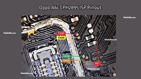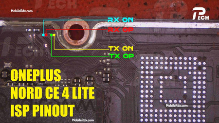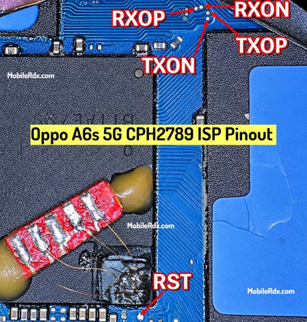

Hello technicians, in this guide, we will show you the working image of the Oppo A6 4G CPH2817 UFS ISP Pinout. By using the ISP Pinout, you can restore the stock ROM, bypass FRP lock, remove MDM Lock, repair a Dead Boot, or clear user data directly through Flash64, UFI Box, Easy JTAG, or Medusa Pro.
Working as a specialist for micro soldering, you work with devices that are brick, locked or dead. Using ISP connection you can communicate directly with UFS chips and there is no need to remove it from motherboard. Layout works for A6 Pro as well as CPH2817 because they use identical code.
What is ISP (In-System Programming)?
The ISP pinout is a “CPU drill”- style solution because you need to touch the data lines on the board layer. On the Oppo A6 4G the test points sit near the UFS memory chip on the main motherboard. You may need to scratch the protective mask or lift a small part of the EMI shielding to see them.
ISP Pinout is useful when:
- The phone is dead (black screen, no boot, no charging)
- FRP is locked and ADB, fastboot or OTG bypass is not working
- You need to dump firmware from a working unit
- You are doing a boot repair or partition restore
- The device shows “unknown” on PC and EDL is not working
Oppo A6 4G UFS ISP Pinout Image:
The ISP pinout provides a without CPU drill solution, allowing you to access the required data lines directly from the board layer. On the Oppo A6, the ISP test points are located near the UFS memory chip on the main motherboard. In some cases, you may need to carefully scratch the protective mask or remove a small part of the EMI shielding to access the points properly.
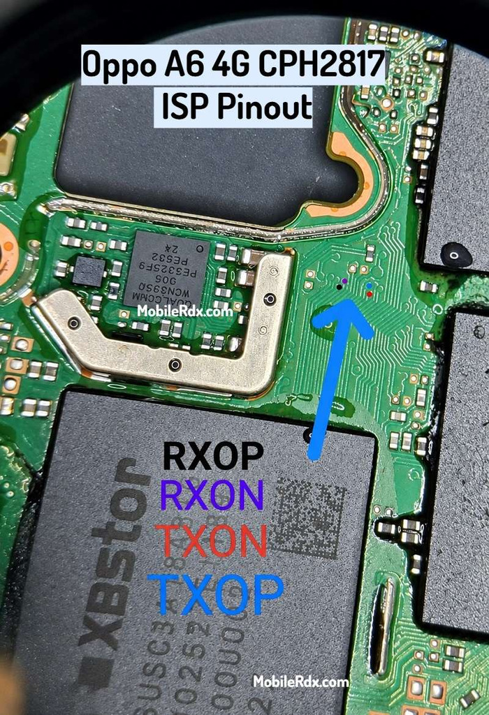
UFS ISP Pin Labels You Need:
- Rst – Reset
- TXOP – Transmit Data Positive
- TXON – Transmit Data Negative
- RXOP – Receive Data Positive
- RXON – Receive Data Negative
- GND – Ground (connect to any ground point)
Required Tools for ISP Pinout
Set up your bench correctly before making any jumper connections.
- UFI Box, Easy JTAG, Flash64, or Medusa Pro
- 0.1mm – 0.3mm jumper wire
- Fine tip soldering iron
- Soldering flux
- Isopropyl alcohol (IPA 99%)
- Multimeter (continuity check)
Oppo A6 4G Key Specifications
| Device | Oppo A6 4G / A6 Pro |
| Model | CPH2817 |
| Chipset | Qualcomm Snapdragon 685 |
| Storage | UFS – 128GB / 256GB |
| RAM | 6GB / 8GB |
| Display | 6.75-inch LCD, 120Hz |
| Battery | 7000mAh |
How to Connect Oppo A6 4G ISP to the UFS Box
- Remove the battery first – prevents voltage conflicts.
- Clean the board area with isopropyl alcohol.
- Solder jumper wires to CLK, TXOP, TXON, RXOP and RXON points.
- Connect the wires to your UFS/EMMC tool following its pinout.
- Double-check every wire with a multimeter for shorts.
- Connect to UFI or Easy JTAG.
- In the software, select Identify UFS/EMMC.
- Use the operation you need: User Partition → Special Task → Reset FRP.
If the connection is right, you will see the UFS chip info appear in the tool window.
Common Issues and Fixes
- No chip detected – reflow the solder joints and check continuity on TXON/RXON.
- Wrong pin order – flip TXOP/TXON so the differential pair matches the tool.
- FRP not clearing – make sure you pick User Partition → Special Task → Reset FRP, not generic erase.
Frequently Asked Questions
The Oppo A6 4G is identified by the model code CPH2817. Because the Oppo A6 Pro shares this exact model code, you can use the same ISP pinout configuration for both devices.
The Oppo A6 4G is powered by the Qualcomm Snapdragon 685 chipset and uses UFS storage.
No, CPU drilling is completely unnecessary. The CPH2817 ISP pinout allows you to bypass the processor and solder directly to the UFS storage test points on the motherboard.
This board is fully supported by major programmers, including UFI Box, Easy JTAG, and Flash64. You will need to use a compatible UFS adapter and load the correct storage profile to establish a connection.
Final Thoughts
The Oppo A6 CPH2817 ISP connection handles dead boot, FRP removal, and backup jobs without chip removal. Confirm the model first, land GND before the data lines, and identify the storage before any write. Clean pads and short wires decide the result on this board.