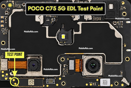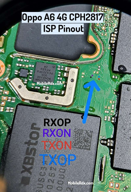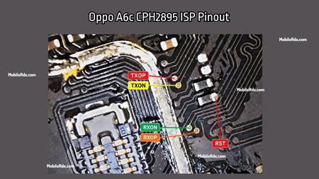

Hello technicians. This guide shows the working pinout for Vivo X300 Pro PD2502F UFS ISP. Using the ISP Pinout, you can restore stock firmware, bypass FRP locking, remove demo mode, and repair a dead boot directly by using Flash64, UFI Box, Easy JTAG, or Medusa Pro.
If you work as a microsoldering technician and deal with bricked, network-locked, or dead phones, you can communicate directly with the UFS chip using an ISP connection. This method can be useful even when the phone is not fully booting but still responds to service modes. The X300 Pro supports MediaTek Dimensity 9500 devices, with BROM and Preloader mode options available for supported devices that still respond.
What is ISP (In-System Programming)?
With ISP technicians can work directly on UFS memory chips that are still soldered to the motherboard. Instead of taking out the chip, you connect jumper wires to correct ISP test points on the board. Depending on the device and service tool this can be used for programming firmware, boot repair, reading and writing storage and for certain tasks related to locking without removing the chip.
ISP Pinout is useful when:
- The device is completely dead and not detected on the PC
- You need to remove FRP, user data, or Vivo account locks
- The stock ROM needs a direct restore through a UFS box
- The device is stuck in a boot loop after a bad flash
- Partition read, write, backup or repair is needed before risky work
Vivo X300 Pro UFS ISP Pinout Image:
Remove the back cover and motherboard shield to access the UFS chip area. Clean board and ISP test points very carefully with IPA to remove dust, flux or other residue. Before making any connections check the pinout image of ISP against actual motherboard and make sure that test points are correctly identified.
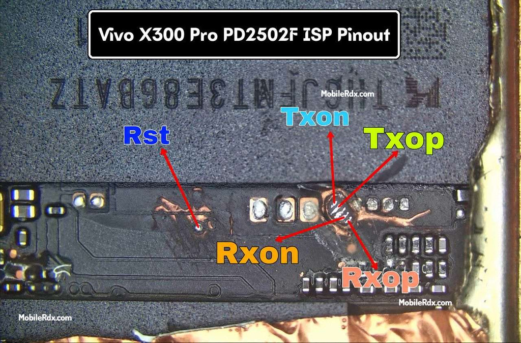
UFS ISP Pin Labels You Need:
| Pin | Function |
| RST | Reset line for the UFS chip |
| TXOP / TXON | Transmit differential pair — data out of the chip |
| RXOP / RXON | Receive differential pair — data into the chip |
| GND | Ground reference for the ISP connection |
Required Tools for ISP Pinout
- UFS Box — UFI Box, Easy JTAG Plus, or Medusa Pro
- Soldering iron with a fine tip and flux
- Enamel-coated copper wire (30 AWG or thinner)
- Tweezers and IPA (isopropyl alcohol) for cleaning
- USB data cable and a Windows PC with box drivers
Vivo X300 Pro Key Specifications
| Device | Vivo X300 Pro |
| Model Code | PD2502F |
| Chipset | MediaTek Dimensity 9500 (3nm) |
| Storage | 256GB / 512GB — UFS 4.1 |
| RAM | 12GB / 16GB LPDDR5X |
| Display | 6.78-inch LTPO AMOLED |
| Battery | 6510 mAh |
| OS | OriginOS 6 (Android 16) |
How to Connect Vivo X300 Pro ISP to the UFS Box
- Remove the battery first to prevent voltage conflicts.
- Clean the board area with isopropyl alcohol.
- Solder jumper wires to the RST, TXOP, TXON, RXOP, and RXON points.
- Connect the wires to your UFS/EMMC tool according to the pinout.
- Check all wires with a multimeter for shorts.
- Connect the device to UFI or Flash64.
- Open the software and select Identify UFS/EMMC.
- First Read/backup persist.
- Check the UFI’s Special Task / FRP operation.
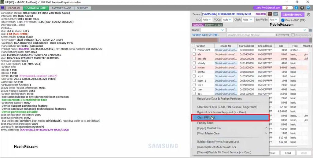
If the connection is right, you will see the UFS chip info appear in the tool window.
Frequently Asked Questions
The Vivo X300 Pro uses the model code PD2502F. Verify this code on the device sticker before running any ISP or service operation.
The X300 Pro runs on the MediaTek Dimensity 9500 (3nm), so both BROM-mode service and UFS ISP pinout methods work depending on the device state.
Yes — AMT and similar server tools support Factory Reset and FRP reset on the PD2502F without hardware work. ISP pinout is needed when the phone is dead or the device is not detected by the PC.
UFI Box, Easy JTAG Plus, Flash64, and Medusa Pro all support UFS 4.1 ISP connections when wired to the Rst, TXOP, TXON, RXOP, RXON, and GND point.