

The Honor X9b Honor ALI-NX1 ISP pinout is useful for mobile technicians and repair professionals who need to access the device’s UFS storage connection for servicing and troubleshooting. In this post, we have shared the tested ISP pinout points that work to restore the stock ROM, bypass FRP lock, remove MDM lock, repair a dead boot, or clear user data directly through Flash64, UFI Box, or Easy JTAG.
What is ISP pinout?
ISP in system programming allows us to access the eMMC/UFS memory directly, with the device still soldered to the PCB (printed circuit board), using a proper box/dongle such as Flash64 UFI, Easy-JTAG, or Medusa.
Using the correct ISP connections, technicians can connect a device to a supported UFS programmer for storage detection, reading and writing, and troubleshooting.
Honor X9b ISP Pinout Image:
Carefully remove the back cover of the Honor X9b and apply controlled heat with a soldering iron. The ISP Pinout enables you to carefully boot into flash mode. So, follow the methods below to successfully boot into ISP mode.
Pinout Labels:
RXOP – Receive Out Positive
RXON – Receive Out Negative
TXOP – Transmit Out Positive
TXON – Transmit Out Negative
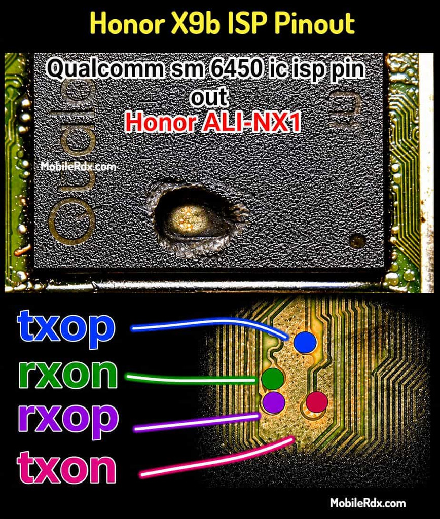
Tip: You can use a microscope or a 10x magnifier to identify the points correctly.
Required Tools for ISP Pinout:
- Make sure your table is set up with the right tools before jumping in:
- UFI Box, Flash64, or EasyJtag
- 0.1 mm – 0.3mm jumper wire
- Fine tip soldering iron
- Isopropyl Cleaner (IPA 99%)
- Soldering flux
- Multimeter (for checking continuity)
Honor X9b ISP Pinout Uses
The ISP connection can be useful for various advanced servicing operations, depending on the supported hardware and servicing tool.
- UFS storage communication and identification.
- Remove FRP or Userlock
- Reading device information.
- UFS memory read and write.
- Firmware and storage-related flashing.
- Data recovery operations where supported.
- Advanced motherboard-level repair.
How to Connect Honor X9b ISP to the UFI Box
- Remove the battery first—prevents voltage conflicts.
- Clean the board area with isopropyl alcohol.
- Solder jumper wires to CLK, TXOP, TXON, RXOP and RXON points.
- Connect the wires to your UFS/EMMC tool following its pinout.
- Check every wire with a multimeter for shorts.
- Connect ISP to UFI or Easy JTAG
- In the UFI or Easy JTAG software:
- Click Identify UFS
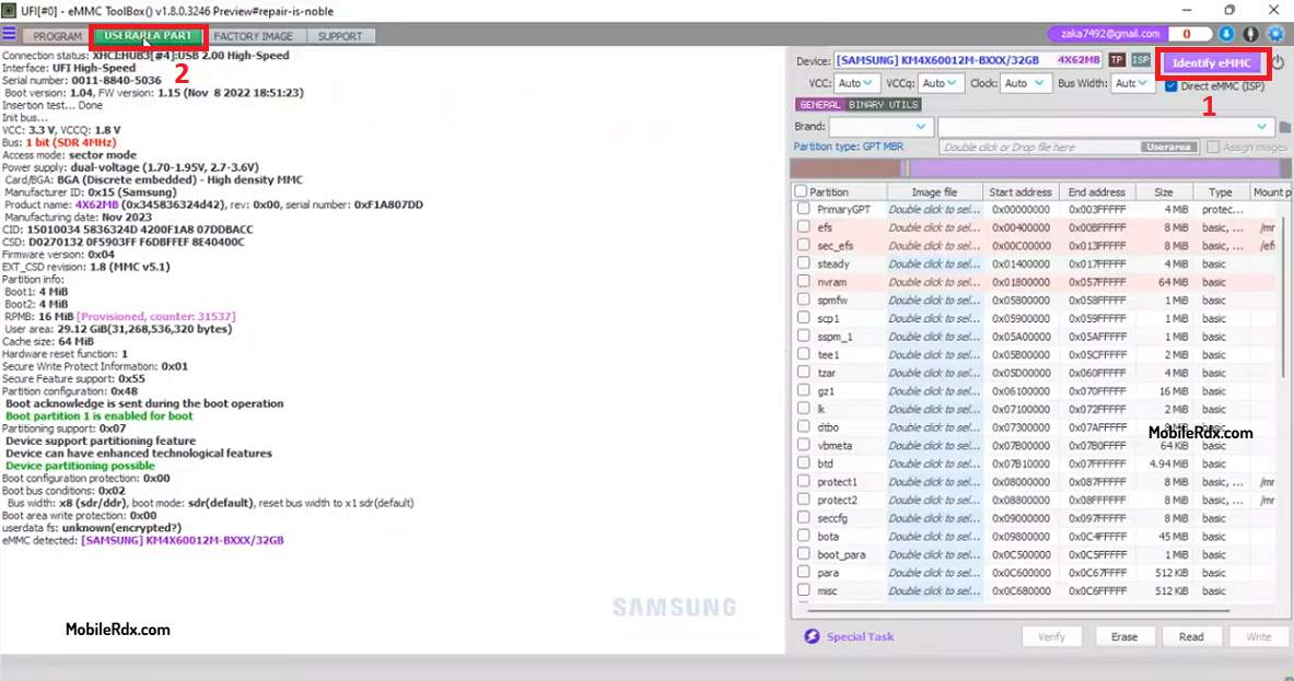
- FRP Bypass: Go to User Partition – Special Task – Reset FRP
- Fix Dead Boot: Select the firmware & click Flash.
- Done.
If the connection is right, you will see the UFS chip info appear in the tool window.